Pattern Editor
Pattern editor is a graphic editor that allows you to create patterns for knitted article details. Calculations are made later based on the patterns in order to obtain text instructions for knitting, generate a pattern in the form of stitches/ rows for applying stitch patterns in “Stitch Pattern Editor”, be able to monitor the process of knitting online, calculate yarn consumption and get the final description.
For video instructions of how to work with the editor, click HERE
Main Principles of Working with the Editor:
- Only one closed outline can be constructed in an editor tab. It means that each pattern detail has to be constructed in a separate tab (one detail – one tab)
- There cannot be any other closed outlines inside the outline. The editor operates based on the principle of creating segments from one point to another. You cannot create a stand-alone point except the first one. Accordingly, you cannot create an outline within an outline.
- The outline has to be closed. If you leave the outline open, you will not be able to save, or calculate the project.
- The outline is calculated into stitches and rows from the bottom up after its construction. In other words, you are supposed to start knitting the detail from the bottom moving upward. If you intend to knit in another direction, turn the outline in the editor so that the beginning of knitting is at the bottom.
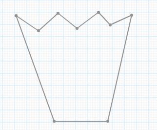
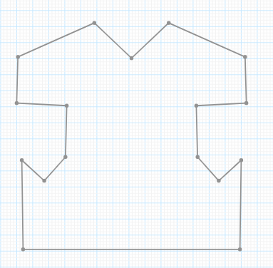
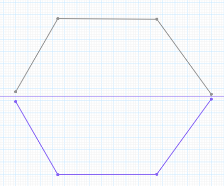
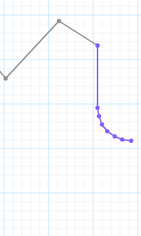
- The detail is supposed to be knitted in a single fabric. Dividing into two or more parts is possible at the top of the outline only, meaning you can knit a detail like this:
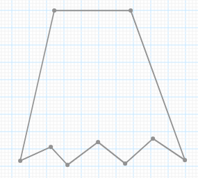
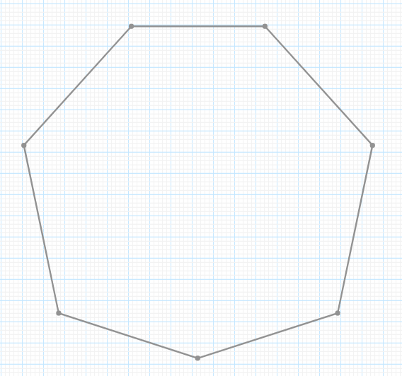
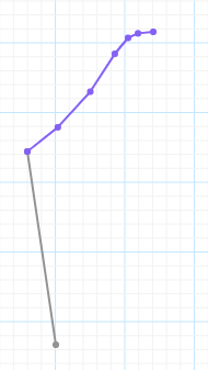
And you cannot knit one like this:
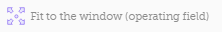
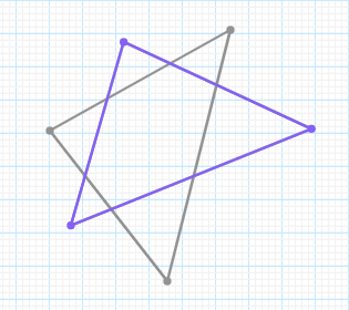
- The outline must not contain any crossing lines:
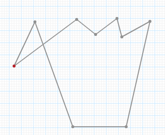
Because in this case there will be more than one outline in a tab.
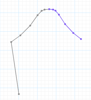
- The outline must not contain any necklines/ recesses on the sides of the outline. For example, the outline shown below will not be calculated:
All the limitations described above are accounted for by the fact that after a pattern has been constructed, it is recalculated into stitches and rows. Calculations are based on complex algorithms, and we are improving them. For now there are some limitations.
Before saving the pattern and creating the project, a check will be made for compliance with the conditions described above. If any of the conditions are not complied with, a corresponding message will be displayed. You will have to correct the pattern so that the requirements are met. The project will be created and saved only after fulfillment of the said conditions.
You can get to the pattern editor from the main website menu, from the website footer menu, from “Basic Patterns Customizer” and from the operating window of the project.
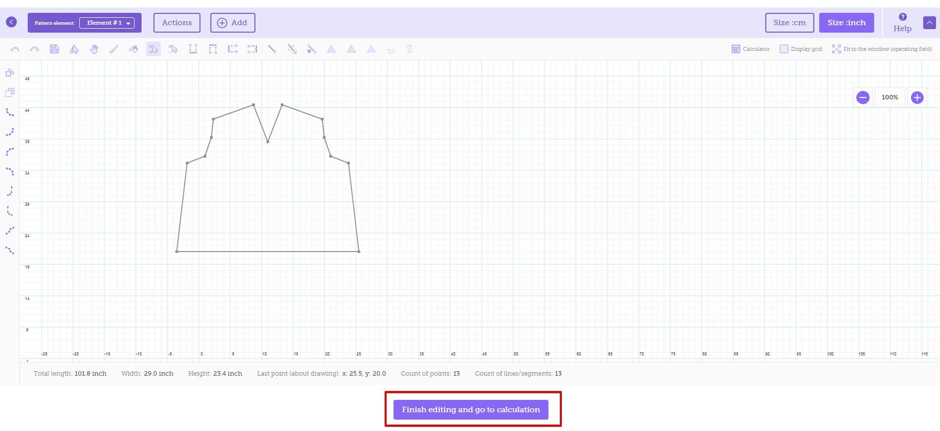
If you get to the editor from the main website menu or the footer menu, the editor will look as follows:
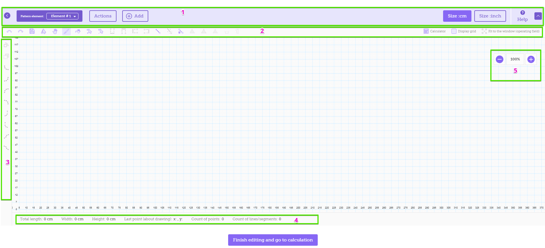
The operating window is located in the center and the pattern is to be drawn in it. There are the following panels around the window:
- Control panel
- Toolbar (horizontal)
- Toolbar (vertical)
- Status panel
- Zoom panel
Let us consider each panel separately:
- Control panel

The panel has the following items:
|
Item |
Name |
Application/ How to Use |
|---|---|---|
|
|
Back/ exit from the editor |
Press it to return to the previously opened website page. |
|
|
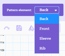
List of elements |
A drop-down list of pattern elements (editor tabs). When selecting an element in the list, you get to a new editor tab to work with the element. By default, the pattern contains one element. New elements/ tabs can be created using the “Add” button which is located to the right on the same panel. |
|
|
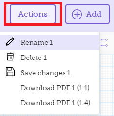
“Actions” |
Selecting an action for a particular pattern element. You can perform the following actions with pattern elements:
|
|
|
“Add” |
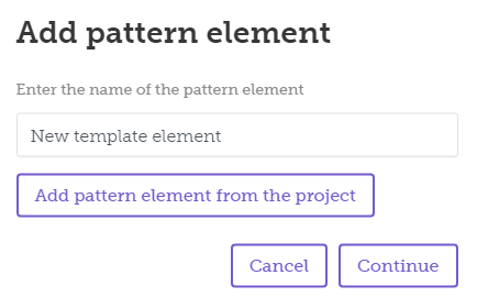
Adding a new pattern element. A new tab is created in the editor. There are two options for use:
The following form is opened when the button is pressed:
Enter the element name in the text field and press “Continue” to implement the first option. Use the “Add pattern element from the project” button to opt for the second variant. |
|
|
“Size:” |
Switching between the editor measurement units: cm or inches. The active button is highlighted in violet while the inactive one is transparent. |
|
|
“Help” |
Access to the help system |
|
|
“Maximize” |
Maximizing the editor to the full screen. A second pressing minimizes the editor to the initial size. |


- Toolbar (horizontal) is located under the control panel. Just like the vertical toolbar, it contains the main tools for creating/editing patterns. All buttons are provided with pop-up tips if there are no captions.
Left part of the toolbar:

Right part of the toolbar:

Below is the description of the toolbar items:
|
Item |
Name |
Application/ How to use |
|---|---|---|
|
|
Undo/ Redo |
Canceling an action/ returning to the initial state if cancellation is not required |
|
|
Save |
Saving the current changes. If the project has not been created yet, you will be given the chance to create it and save the project name, description, date, status, etc. |
|
|
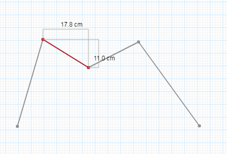
Measure |
Shows the distance on the X and Y coordinates between the extreme points. Apart from the said parameters, some additional information is displayed in the status panel:
|
|
|
Drag |
Dragging a figure around the operating window based on the principle of dragging and dropping. |
|
|
Draw |
The main tool for creating points and segments. When clicking the mouse button, you get the first point; another click will create a new point which will be connected with the previous one by a segment. The following information is then displayed on the status panel located under the operating window:
|
|
|
Clear |
Clears the operating field completely. Before clearing, you will see a warning message to prevent accidental deletion of data. |
|
|
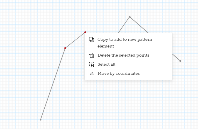
Select points |
Selecting one or more point to perform further actions available in the drop-down menu (right mouse button click).
The following actions are available:
|
|
|
Unselect |
Clears selection of points if any |
|
|
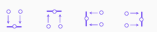
Buttons for moving segment points |
Allow moving one point of a segment relative to another one. The following options are available:
|
|
|
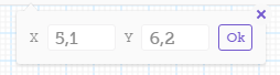
Create point by coordinates |
Creates a point connected with the original point by a segment. The last or the first point of the open outline is the original point. You specify the X, Y coordinate values and get a new point at the set distance: |
|
|
Move point/ points |
Moving by coordinates. This is to allow the shifting of all points by a set value by the X and Y coordinates: |
|
|
Delete point |
Deleting selected points. Deleted points are replaced with a segment connecting neighboring points if a deletion takes place in a closed outline or if the points are not extreme points of an open outline. If extreme points of an open outline are deleted, the segments are deleted too.
|
|
|
Open figure |
The option is available only if the figure is closed. If the outline is open, the feature does not work. In order to open an outline, first of all you need to select two points (“Select points”), then press this button and the segment between the points will be deleted – the outline will be opened. |
|
|
Delete line |
Also allows opening an figure. But, unlike the feature described above, this one does not require any preliminary selection of points. The button is only available for a closed outline. If the outline is closed, press the button and bring the cursor close to the line that has to be selected. The line will be highlighted in violet. Click the mouse button to delete the line.
|
|
|
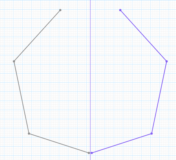
Horizontal symmetry |
Creating an outline symmetric to the original outline horizontally. After application, the newly created shape always forms a closed outline.
|
|
|
Vertical symmetry |
Creating an outline symmetric to the original outline vertically. After application, the newly created shape always forms a closed outline.
|
|
|
Calculator |
Accessing the calculator if you need to make some calculations |
|
|
Display grid |
Displaying/ hiding the grid of the operating area |
|
|
Fit the figure/ outline to the operating window |
Making the figure fit into the operating field completely as it has the largest possible size at the same time. |


 . A positive value of the X coordinate makes the points move to the right while the negative one – to the left. A positive value of the Y makes the points move up while the negative one move – down.

 . A positive value of the X coordinate creates a point to the right of the original one and a negative one – to the left. A positive value of the Y coordinate creates a point higher than the original one and a negative value – lower.
 . A positive value of the X coordinate makes the points move to the right while a negative one – to the left. A positive value of the Y coordinate makes the points move up while a negative one – down.


- Toolbar (Vertical)
Continuation of the horizontal toolbar. It contains the following buttons that are provided with pop-up tips just like those on the horizontal toolbar.
|
Item |
Name |
Application/ How to use |
|---|---|---|
|
|
Rotate shape/ outline |
Rotating a shape around its axis to change its position. After the button is pressed, another shape, completely equivalent to the first one, but in violet color, appears in the place of the main outline. You can rotate the shape using your mouse. Choose the required position, click your mouse and the outline will take the new position.
|
|
|
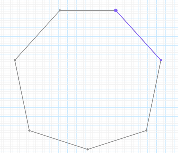
Flip |
Flipping the shape along the OY axis (vertically) or the OX axis (horizontally). The figure below shows vertical flipping:
Just like in the case described above, the violet color shows the new position of the shape that will be established after a mouse click. |


Creation of curves (the following 8 buttons on the vertical toolbar) will be described separately. Curves allow adding the most frequently used lines (round neckline, armhole, sleeve cap, convex/ concave line) to a pattern element quickly. All curves consist of several points and several segments connecting them. Certain proportions between points are observed within the curves to obtain a result as suitable for the task as possible.
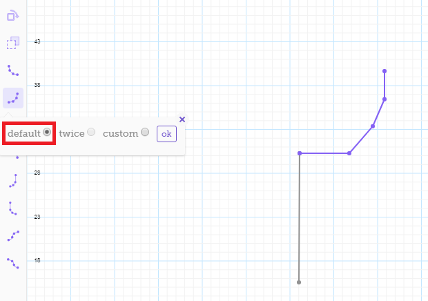
All curves have three options of use:
- “Default” mode. The curve is created by moving the mouse from the last created point. The mode is available for an open outline only.
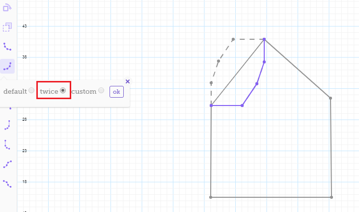
- “Twice” mode. The curve is inserted instead of the existing segment. The mode is available for a closed outline only.
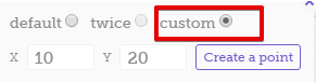
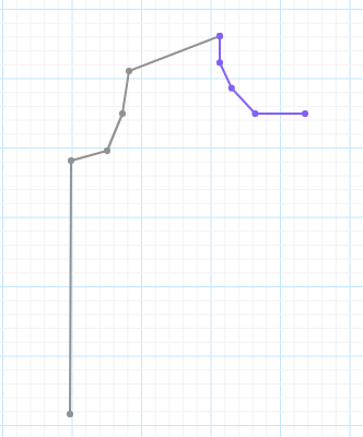
- “Custom” mode. The curve is created based on coordinates. A distance is set on X and Y coordinates. The curve is inscribed into the set rectangle. The mode is available for an open outline only.
|
Item |
Name |
Application/ How to use |
|---|---|---|
|
|
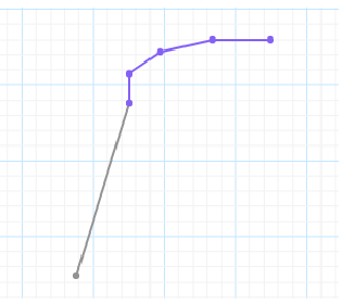
Necklines right and left side |
The first line allows you to construct the neckline from the upper point down (the right side of the neckline):
The second line goes from the lower point up (the left side of the neckline):
|
|
|
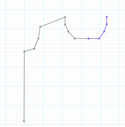
Convex/ concave line |
The first line allows constructing a convex line when moving from the lower point up and a concave line when moving down:
The second line, on the contrary, forms a convex line when moving down and a concave one when going up:
|
|
|
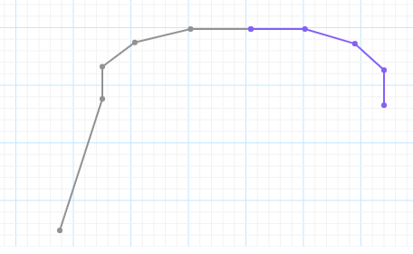
Armhole lines |
The first line forms the armhole when moving up from the lower point:
The second line forms the armhole when moving down from the upper point:
|
|
|
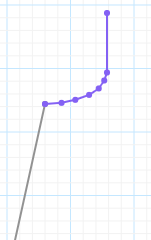
Sleeve cap lines |
The first line forms the sleeve cap when moving up from the lower point:
The first line forms the sleeve cap when moving up from the lower point:
|


Status Panel
The panel is located under the operating window of the editor:

It displays the following information about the outline/ shape:
- Total length of segments
- Shape width
- Shape height
- Coordinates of the last created point
- Number of points the outline consists of
- Number of segments the shape consists of
If the “Measure” tool is used, information is displayed for the selected range only. In other cases, information covers the entire outline.
Zoom Panel
The panel is located in the upper right corner of the operating window. It allows zooming the shape in and out to facilitate working with it.
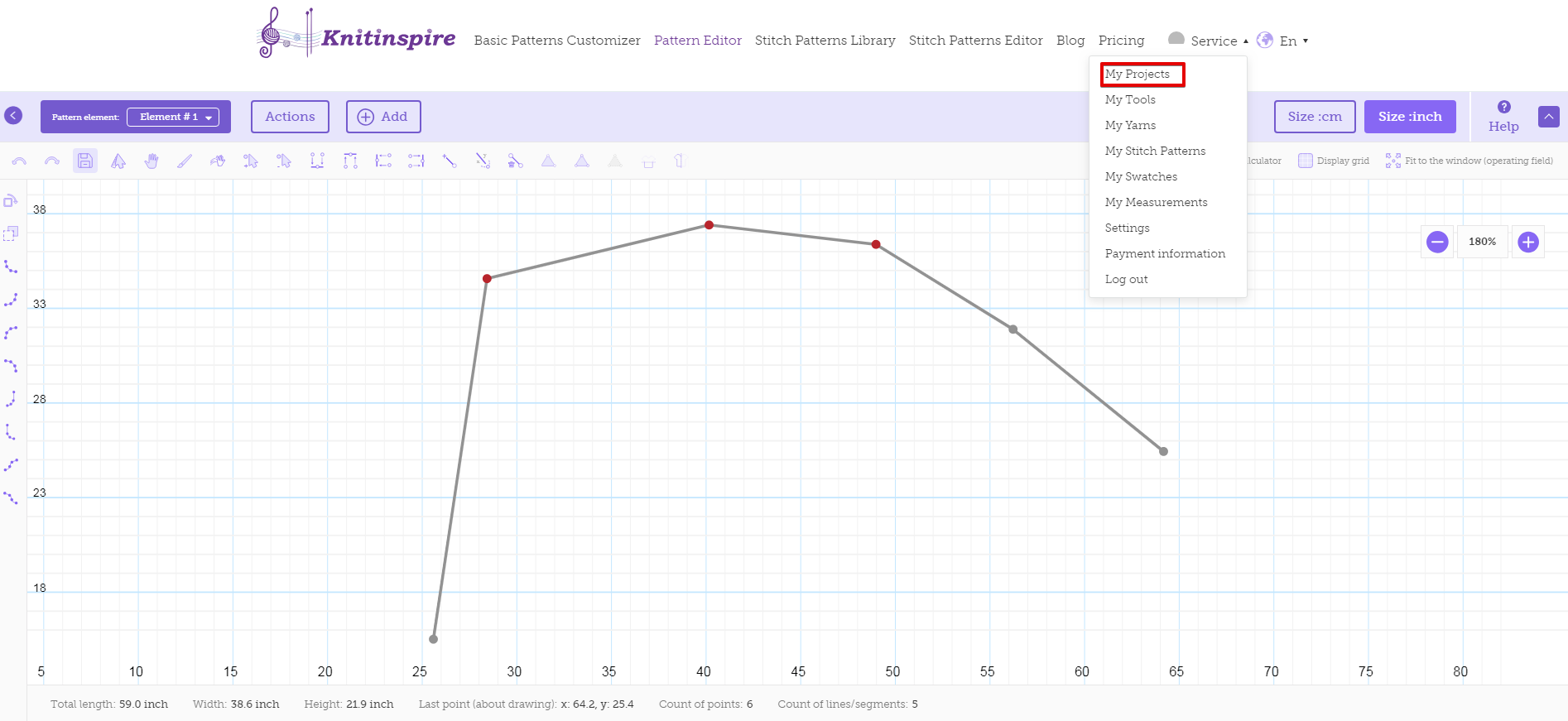
There is a “Finish editing and proceed to calculations” button under the operating window of the editor. Click it when you finish working in the editor to create a project and save information. After the project has been created, you will be given a choice to proceed to the following stages of working with the project (adding data of a swatch/ swatches, adding stitch patterns, etc.)
You can find the project you have created in the “My Projects” section of your account. You can access your account by pressing on the profile picture in the upper right corner of the website.